Before anything else, an important note: I don’t have any degree in electrical engineering. So if anything is wrong, feel free to correct me. However here is the guide.
After a few asked, I made a wiring diagram of my eGPU project.
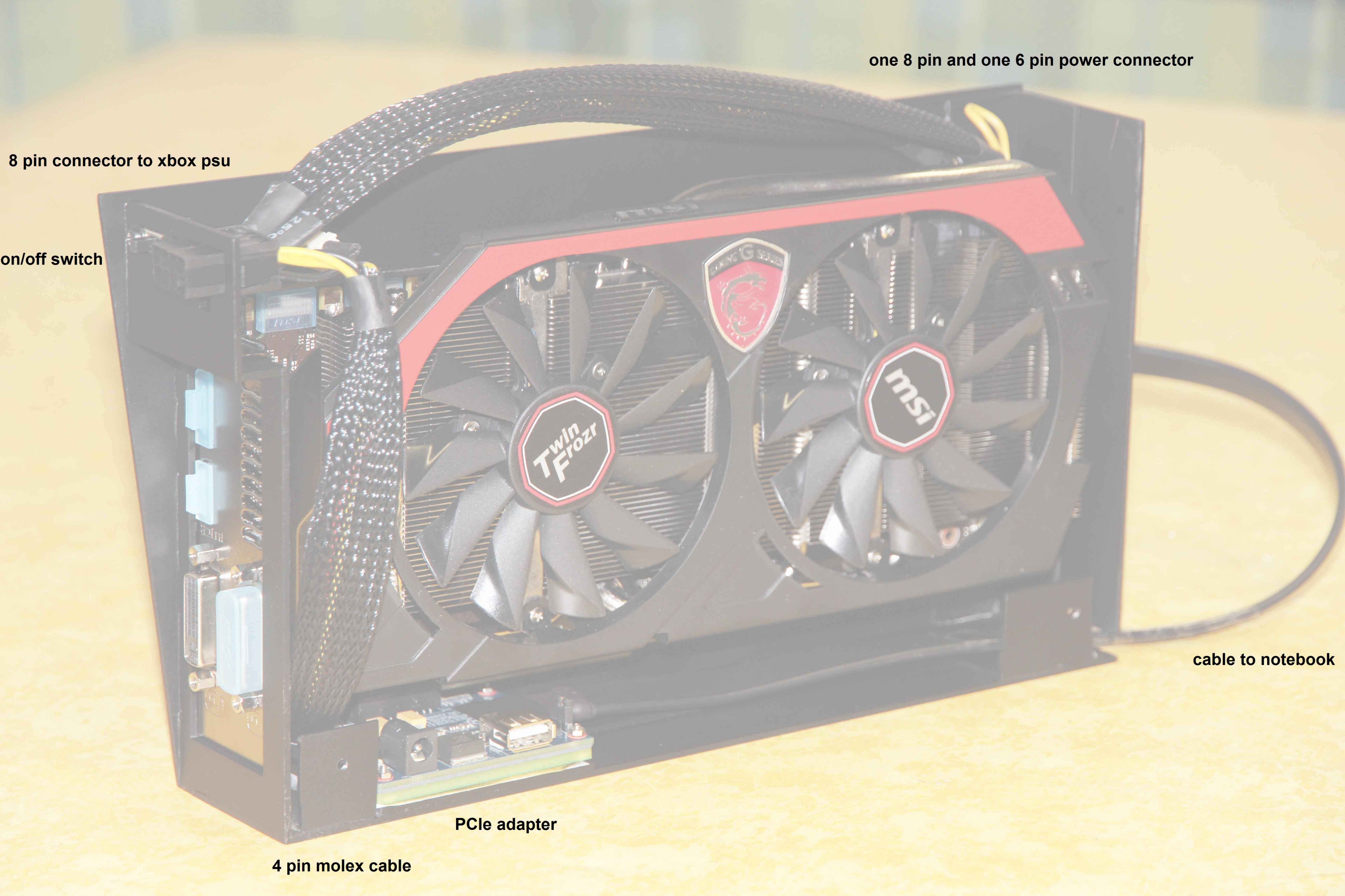
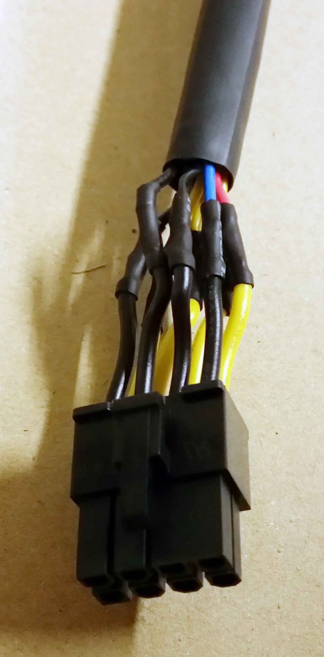
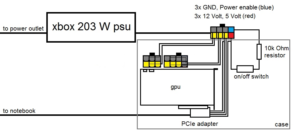
It’s important that you have experience in soldering and basic electronic knowledge. On the left is the connector from the Xbox psu to the eGPU case. This big cable contains four thick, two ground (black) and two 12 Volt (yellow), wires. There are also four thinner wires. Again one ground (black), one 12 Volt (yellow), a red 5 Volt and a blue power enable wire. To start the Xbox psu, you have to connect the blue with the red wire. In between those two wires I inserted a 10k ? resistor and an on/off switch.To be able to unplug the power connector, these eight wires are mounted to a male 8-pin connector. The case has the corresponding 8-pin female connector, which is glued to it.
The PE4L V2.1 PCIe adapter I bought, is powered by 5 and 12 Volt. It has a mini molex connector, which is wired up to the Xbox psu connector.
The 6-pin and 8-pin power connectors of the graphics card use each one ground and one 12 Volt pin of the connector. Don’t forget to connect all of the pins of the gpu connector to the corresponding voltage level.
Feel free to comment, if you liked this post or have questions.