This project took many weekends over this summer. Originally I wanted to do a build log over this time to show its progress. But whenever I found time, I rather continued the casemod instead of writing here. At least I took many photos over this period of time to document its progress.
Over the last six years I had the Cooler Master HAF 922 computer case. At that time I liked the design, but a few reasons lead to a wish for a new case. First of all the build quality of the old case was not up to today’s standards. The lack of USB 3.0 ports in the front was annoying for using fast USB storage media. But overall it was okay, until I saw the In Win 805 last winter. The simple and high-quality design in combination with the tempered glass side panel made me want to build a new PC in this case.
Since I was busy with work for my bachelor thesis, the “New PC”-project was paused until June. Over this time I thought what features of a PC would be important for me. A quiet, good-looking, powerful and cheap PC is the vision of every PC owner. But often powerful PCs require big, noisy air coolers. And cheap doesn’t go with any of the others. So one must evaluate, which objectives are more important.
I also realized that the In Win 805 wasn’t the perfect PC case. I missed the option for an optical drive. But since my new PC should have watercooling, the support for radiators bigger radiators (A 360 mm in the front and 120 mm radiator in the back) could potentially compensate for that. The support of the HAF 922 wasn’t satisfactory (A 240 mm in the top and 120 mm radiator in the back). But the price of over 170 € at the time held me back from immediately buying the In Win 805.
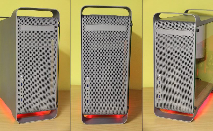
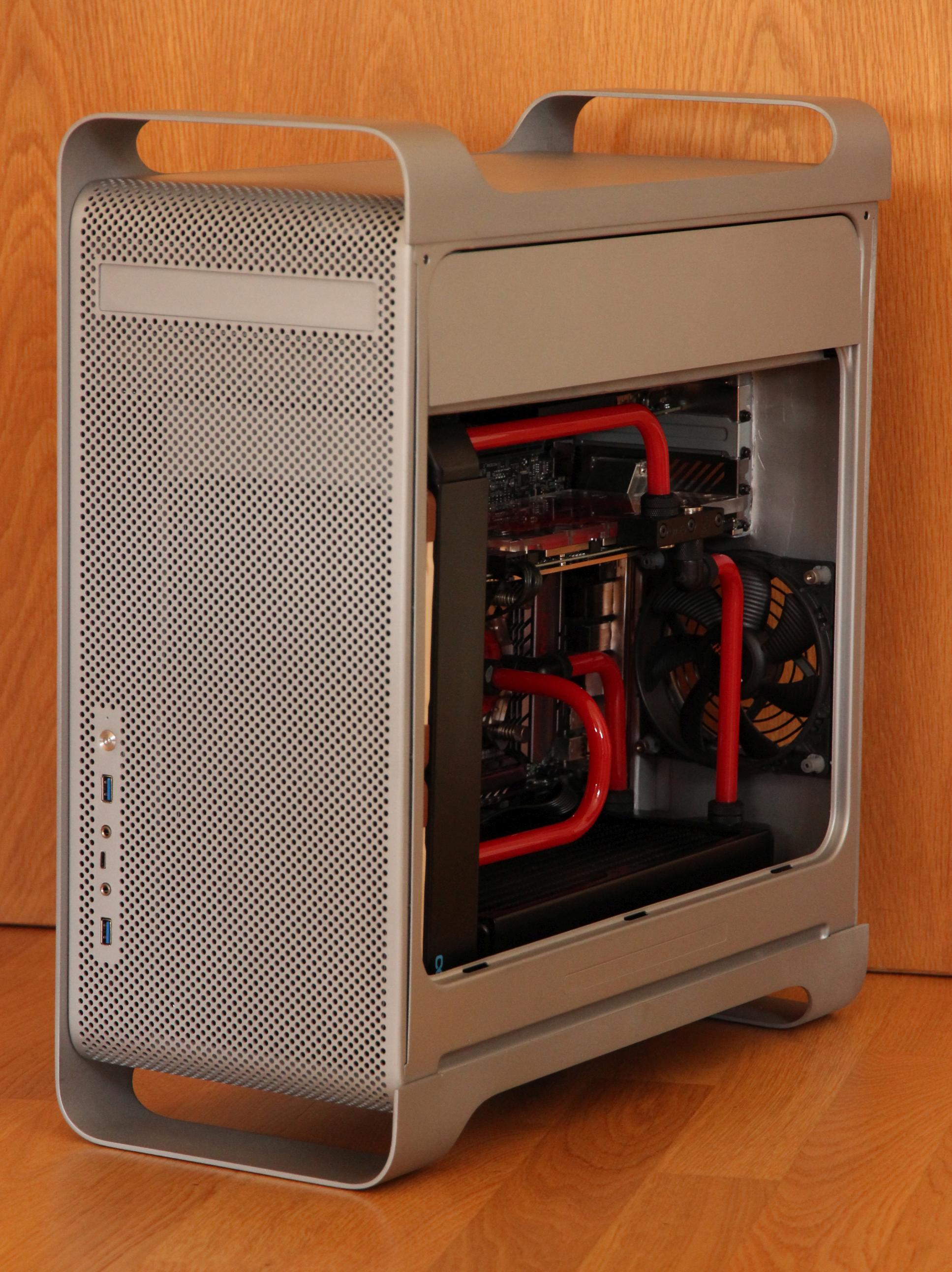
After looking around in build logs on many forums, I found an other candidate for my new PC case. A few people bought old Apple Power Mac G5 cases and changed them internally to fit ATX mainboards. Most of them used professionally made, lasercut conversion kits available for around 100 €. Those kits let you mount an ATX mainboard and use the back IOs. But those kits didn’t made the Apple Power Mac G5 watercooling-ready. Considering my experience and knowledge I gained with the eGPU project, I thought, I could design a few lasercut aluminium pieces.
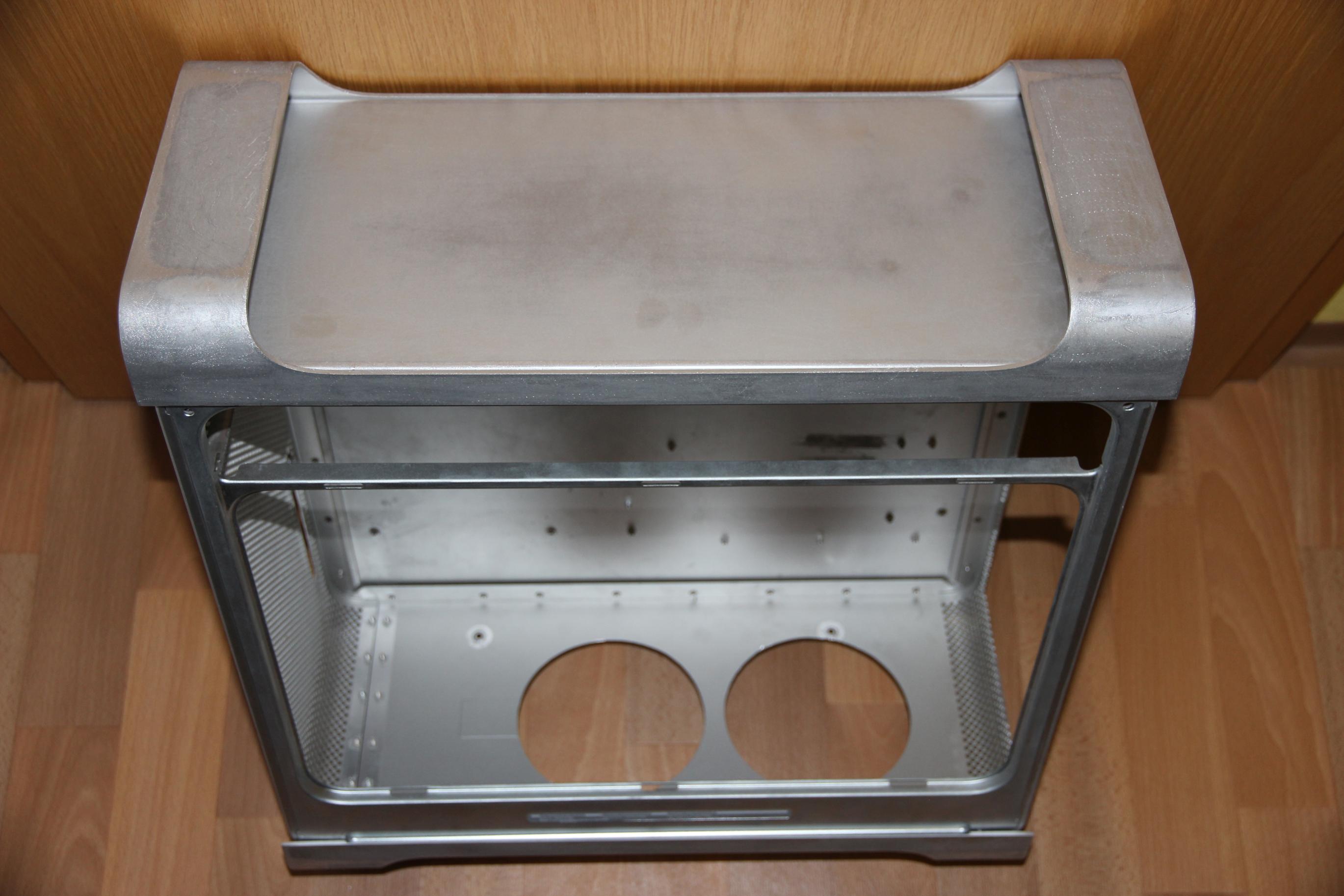
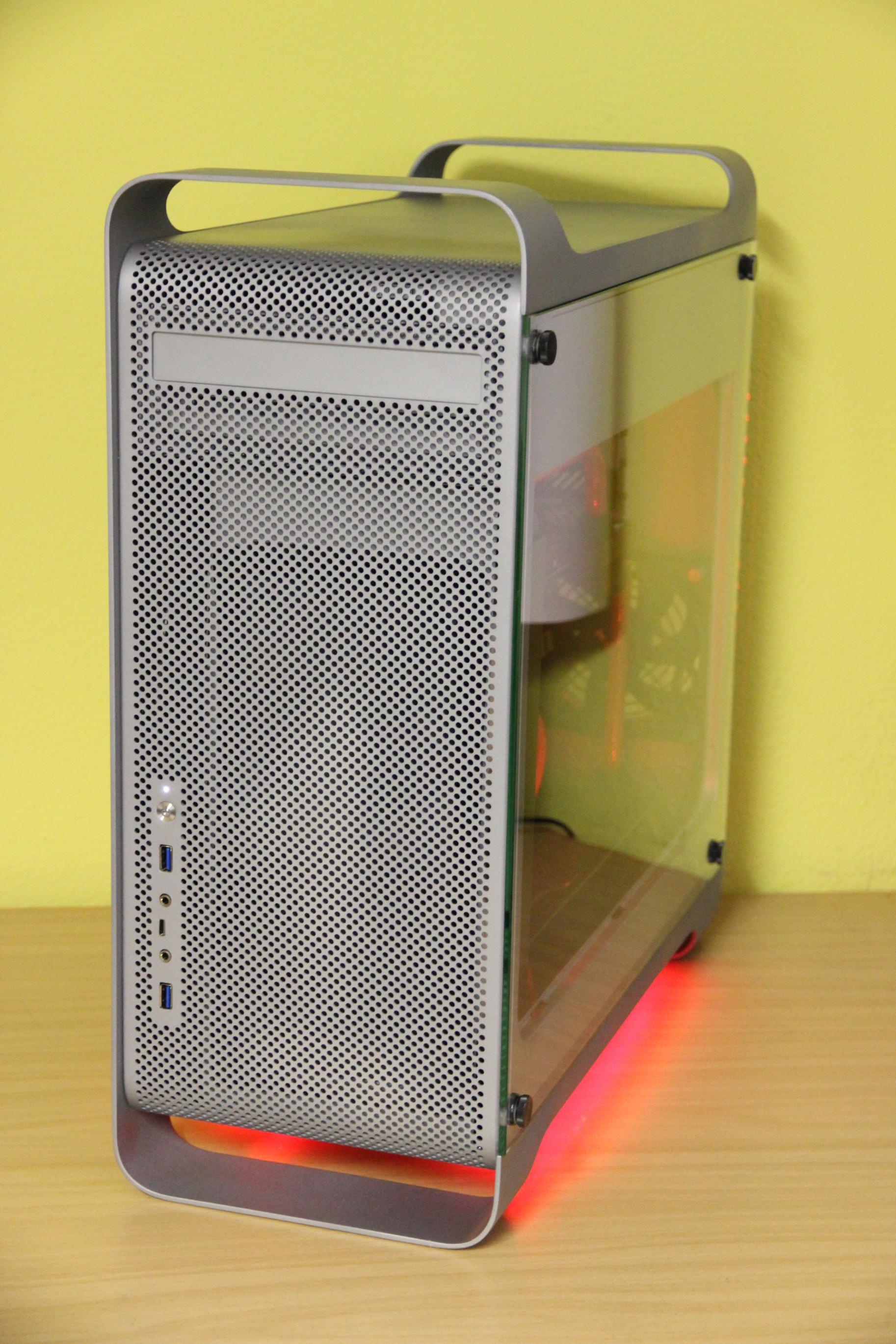
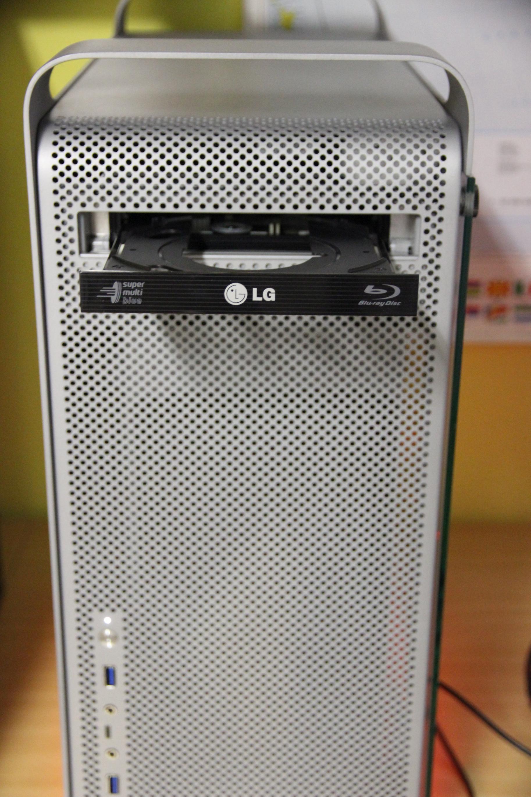
Since a lot of the Apple Power Mac G5 cases on Ebay were in a poor condition or overpriced, it took a few weeks until I finally got my case. Because the Apple Power Mac G5 series is now over 10 years old, many things have to be changed. The front USB 2.0 and firewire connectors aren’t up-to-date. The back IO and the mainboard tray have to be changed to fit a µATX mainboard. Also there should be 280 mm radiators in the front and bottom. The optical DVD should be replaced with my BluRay drive. Since I liked the tempered glass side panel of the In Win 805, this casemod should feature likewise a tempered glass side panel.
Specifications:
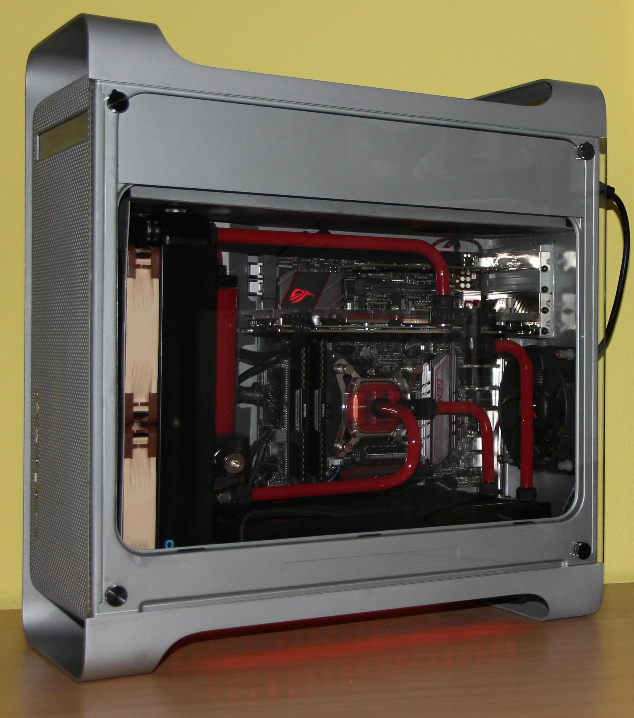
- Intel Core i7-6700K with Watercool waterblock
- Gigabyte GTX 1070 G1 Gaming with EKWB waterblock
- 16 GB Corsair RAM
UPDATE: Added DFX-Download of the lasered parts
As always, feel free to comment, if you liked this post or have questions.
Hey man, I’m a 20 year old pc enthusiast and I have just managed to get my hands on my father’s old g5. I’m looking to mod it and this is by far the most gorgeous g5 I have seen to date. Would you recommend buying a kit from laser hive or making my own plans and getting them cut? Please get back to me, as your build is my inspiration. Amazing work, thanks 🙂
Hey, thanks 🙂
It depends on your skillset and how you value your time.
Those conversion kits are about 100€, all my lasercut pieces were 75€.
If you need any other lasercut pieces (besides the back) to complete your mod, I would get everything lasercut including the backpanel.
Also if you need any help, the cad-file or have questions, just ask.
Hey, what an awesome project. I would like to try and make my own, would you mind sharing plans / files you already have?
How did you make the new parts look so original? Would did you attach them?
Thanks,
Ulf
Very nice, one of the cleanest I’ve seen.
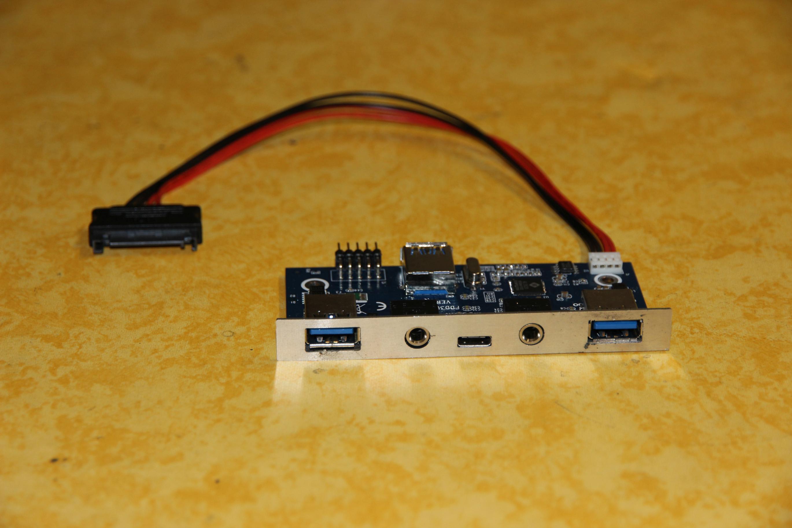
I’m collecting ideas for my own version and I’m interested to know where you found the board for the front I/O.
Thanks.
Hey,
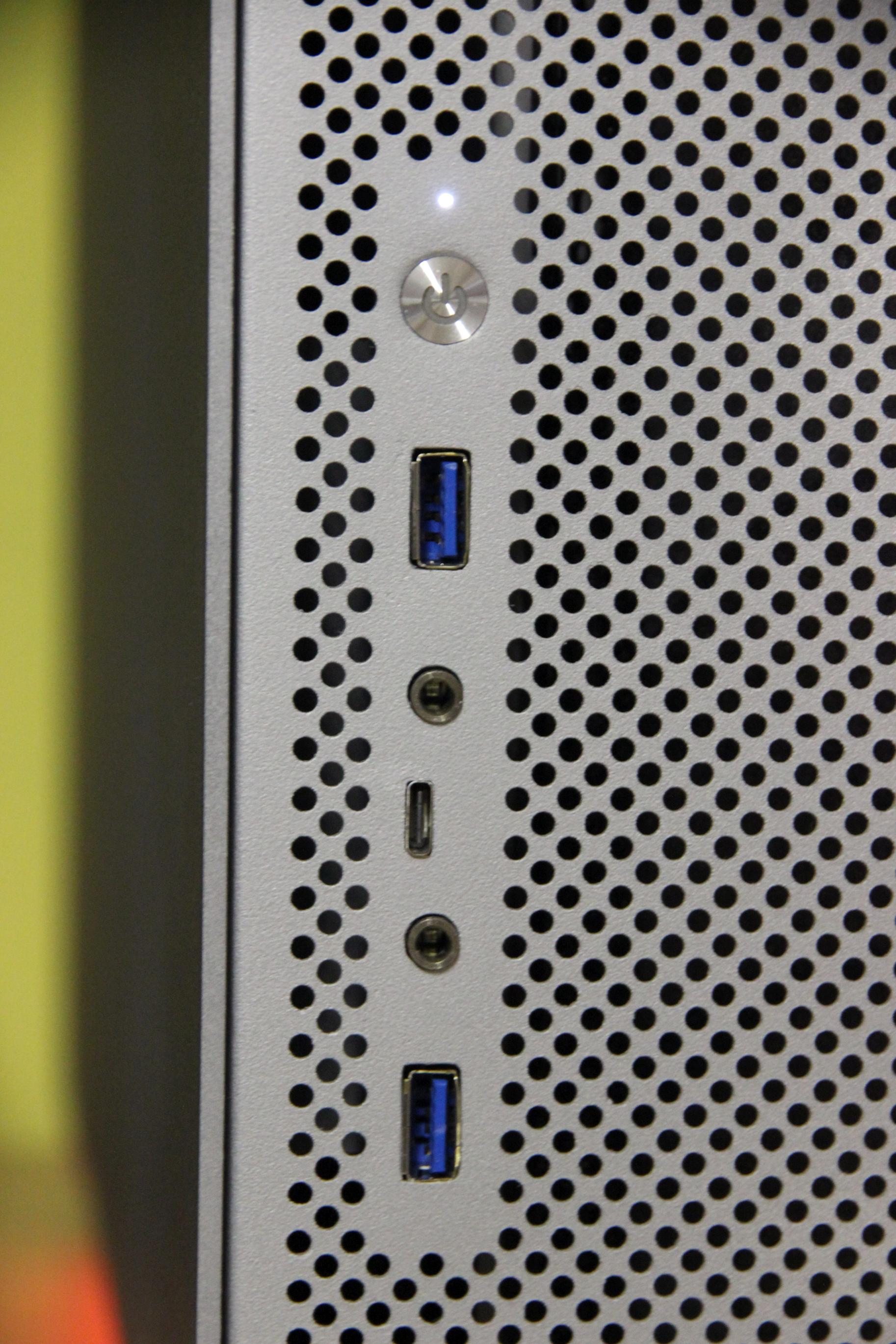
search ebay or aliexpress for “USB 3.1 Type C audio front panel”.
They should cost about $14.
This looks absolutely gorgeous! Also a big thank you for sharing your lasercut files, which front IO you used etc. How did you mount the tempered glass and how much did you end up paying to have it cut to size or did you do that yourself?
Keep up the awesome work!
Thank you.
I bought the tempered glass from a local shop for 50€. They cut it to size and drilled the holes.
The side panel is mounted with threaded rubber standoffs I glued onto the aluminium side. Four thumbscrews hold the panel in place.
Is the dxf file corrupted for anyone else? I cant seem to extract it from the zip (error 0x80004005). Could you possibly email the file directly to me?
Aside from that this looks awesome!
Works for me, I used 7zip to extract the zip.
I emailed you the file.
Thanks!
Awesome project. Planning to do something like this to my old Mac Pro. May I ask how you got the front I/O looking so nicely? All I can think of is:
– What aluminum did you use to get the texture looking so similar?
– How did you glue and cover the marks? (Which products)
I’d be grateful to hear about your experience.
Hey,
thanks.
I used metal spatula [1] to connect my lasercut parts to the case.
Anyplace where to much metal spatula was applied, I removed it with sandpaper.
Then everything was sprayed with paint.
Someone asked a similar question in the update post [2].
Have fun with your project!
[1]: https://www.motipdupli.com/en/INT/lang/products/presto/putty-products/ipg-1095/tm-1095.html the 250g variant was enough
[2]: https://www.tomrei.com/2017/02/update-apple-power-mac-g5-casemod/
Thanks for the quick response! Did you cut out the parts from your replaced side panel?
No, I ordered the parts online. See the dfx file at the end of the post.
So I plan to use your back plate, Motherboard tray and front panel shield in my build, as I think I can get the pieces laser cut where I live.
Quick questions though, for your motherboard tray will I need to make custom standoffs or do they use the original standoffs?
For the backplate are you using the G5’s mounting section for like the Video card? I guess another question would be, is your board MicroATX?
And for the Front Panel connector, will apples power button connector fit on my motherboard or will I need to mod that too?
https://imgur.com/oGL5QTL
And for clarification, Part 1 is the backplate, 2 is the Front IO shield, and 3 is the motherboard tray?
I used the standoffs from an old case.
The video card mount is in its original place.
Yes. Mainboard: ASUS ROG Maximus VIII Gene
The power button is connected with three wires (Ground, Led+, Power). I added a connector to these wires so I can easily plug it onto the mainboard pins.
Yes. But I updated the dxf-File (new version I uploaded today).
hello can guide me how to build the setup. already lasercut the item.
hello can guide me how to build the setup. already lasercut the item. thanks
Please could you email me the dxf’s too please, the zip file isn’t working for me
Can you please try again?
Should work now.
Hey !! You have a really nice mod and you inspered me to improve on mine :^) (I have a Laser Hive kit)
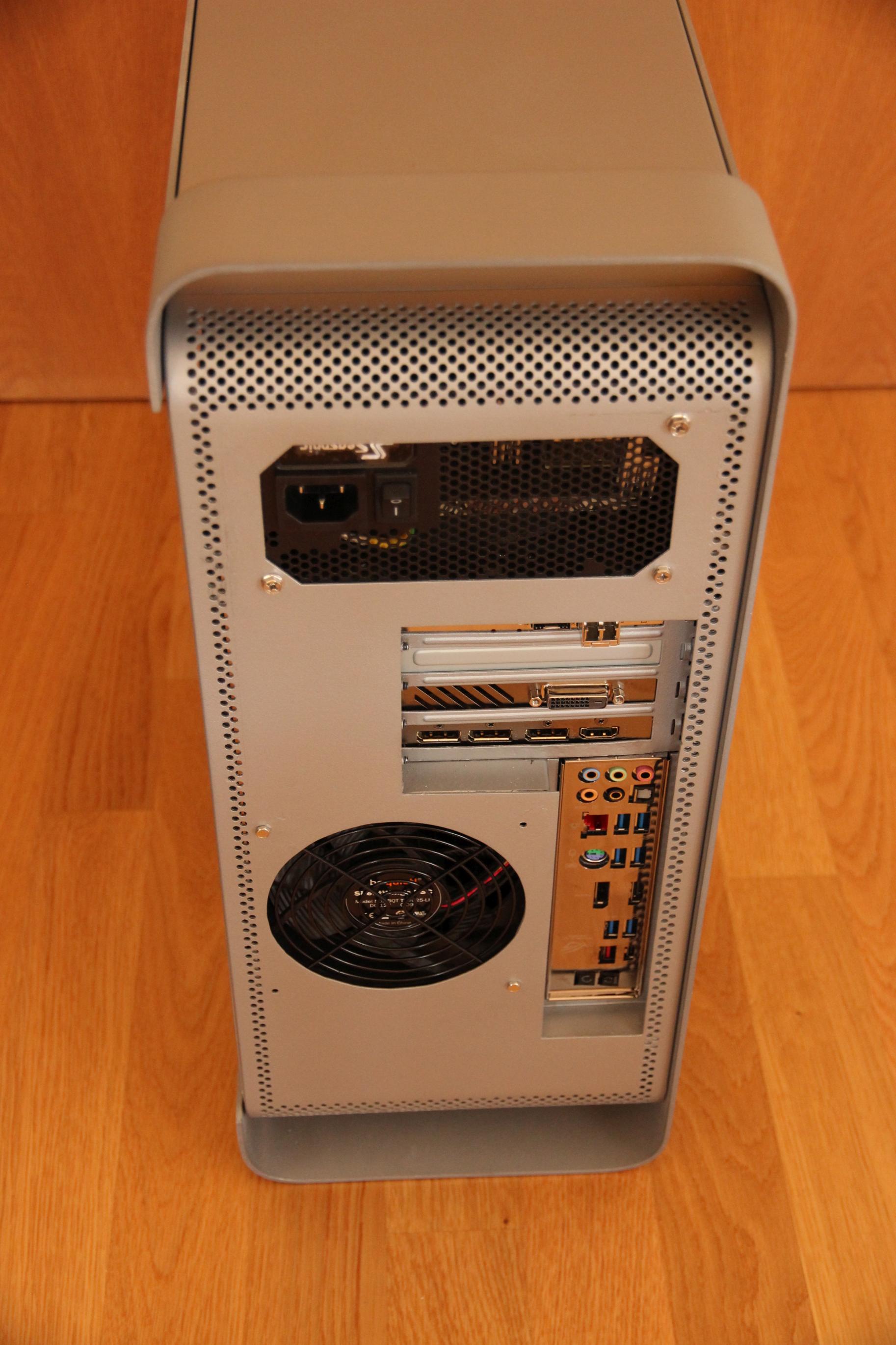
The thing is I want do make the back side just like yours, which blends perfectly with the original metal of the case, but I have a question about the PSU placement.
Is it safe? I see you used epoxy glue on the backside and used aluminum filler as well but can all of this hold a 1.2kg weight of a PSU? Or did you used the internal top shelf as a support for the PSU?
I don’t have to say how much of a desaster it would be to have your PSU falling on your GPU.
Hey,
I used spare aluminum parts to double the layers over the glued parts (left and right of the PSU).
What’s important is that you use clamps over the night to press it together to get the best result.
Otherwise it shouldn’t be a big problem.
In my case the PSU also rests inside on the PSU shroud, which will definitely help while transporting the case.
Have fun building your case! 🙂
Happy new year !!!!
Thanks for the reply !!
I’ll have to think of a solution for a shroud in my case, since for my case (no pun intended) I had to cut off the top shelf for the 7 PCI lanes of the laserhive kit to fit.
Hi Tom,
I know this is a few years old now, but thank you for sharing your build, it’s honestly so inspiring, well done! I have new ambitions to mod my old G5 now. Thank you also for supplying the DXF file. I’m looking at the design on Autodesk Viewer and am kinda confused at what I’m looking at. Could I get you to explain what each piece is and does? I have zero experience in any CAD programs and was planning to print yours as it is. Also what grade of aluminium is your cut? I have options here to cut grades 5005, 5083, 2024 and 6061. Your help is much appreciated.
Many thanks,
Bryan
Hi Bryan,
thanks!
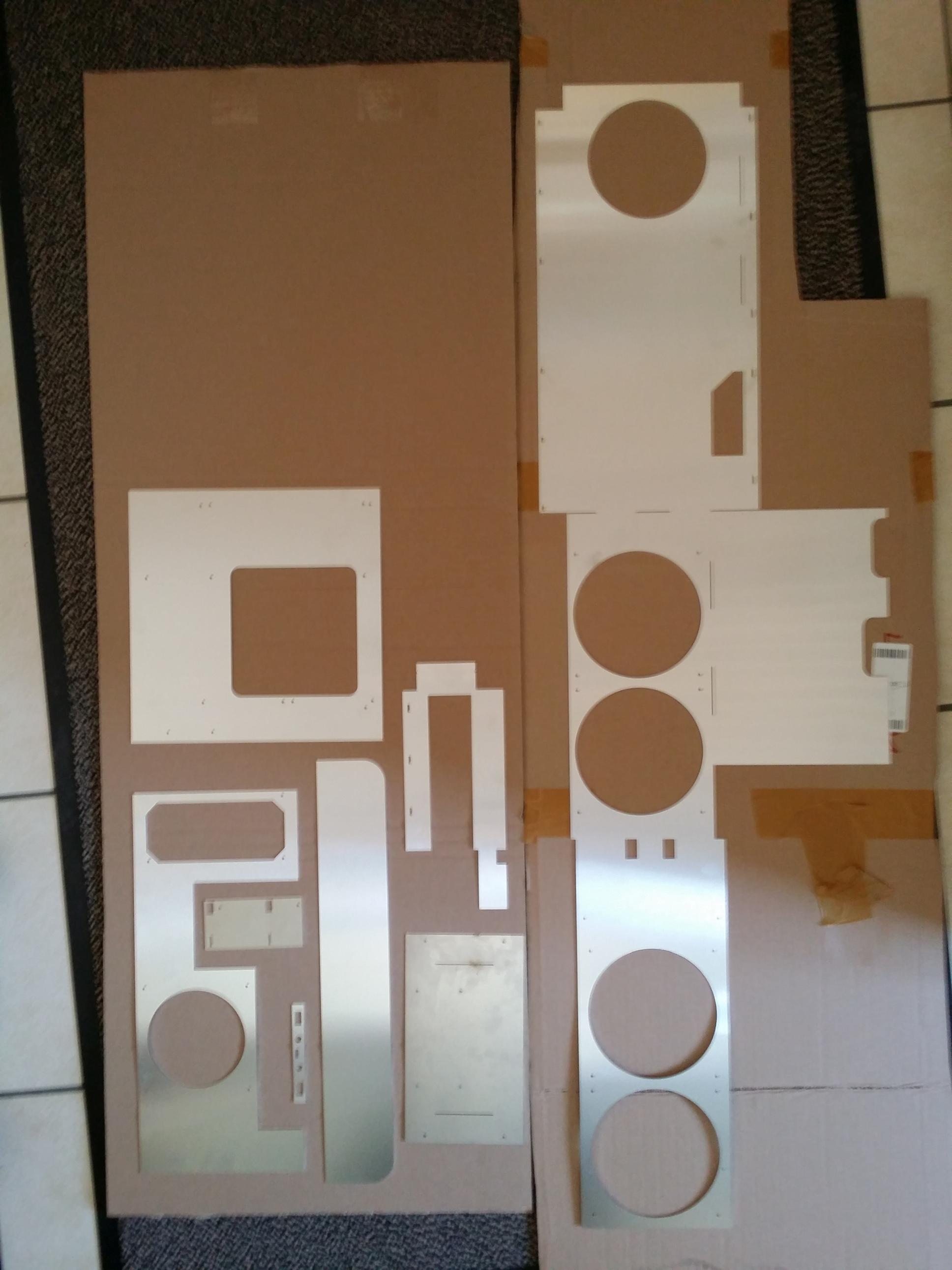
Have a look at the picture called ‘The lasercut pieces’.
On the right side there is the inside piece for fan/radiator mouting. It’s one big piece, which has to be bent mulitple times. The part on top sits underneath the PSU and the 5.25″ BluRay player. The middle piece is for the front fans and to cover the mainboard cables. The lowest part is for the bottom fans.
On the upper left you can see the mainboard tray. It can be screwed to the existing standoffs and will have matching holes for ATX standoffs.
The lower left piece is for the backside, there is room for one more 120mm fan.
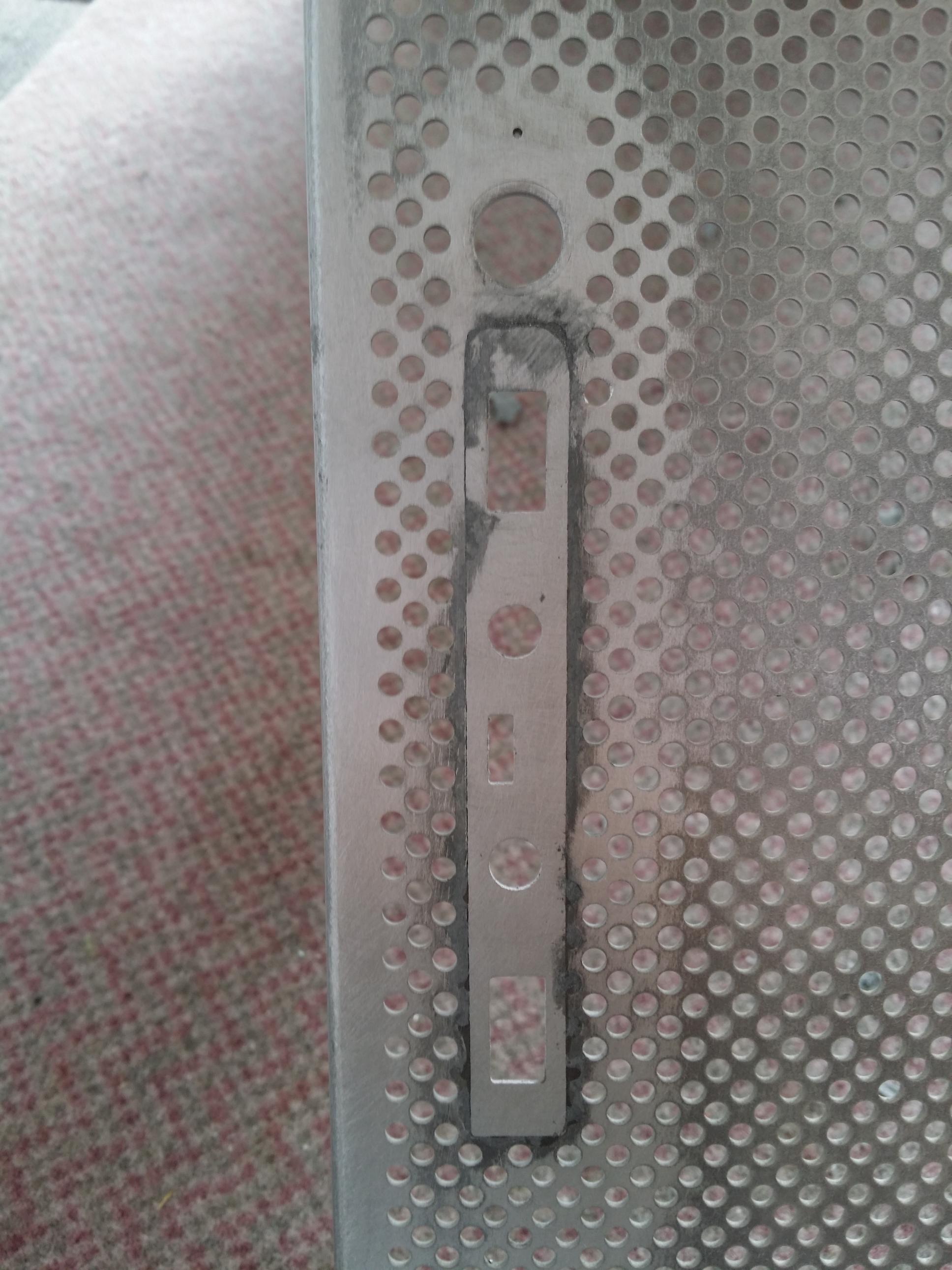
The little piece next to it fits to the front panel connectors (2 USB-A, 1 USB-C, 1 microphone, 1 headphone).
The long piece with two rounded corners sits underneath the glass sidepanel and hides the PSU cables.
The turned aroung U-shaped piece needs to be bent four times, glued to the backside piece and will support the mainboard I/O shield in the back.
I didn’t order any specific kind of aluminium, at least none of the emails says anything about it, just 1mm thickness.
Also if you have the option to order waterjet instead of laser cutting maybe try that, since you get cleaner cuts so you need to use less sandpaper.
Best regards,
Thomas
hi Tom, hope you see this. I am attempting something similar. How did you attach the front panel board to the case? I can\’t think of a good way to attach the board to the case so that it lines up with the lasercut piece in the front. Thanks!
Hello Tim,
do you mean the IO panel piece or the piece, which holds the front fans and radiator?
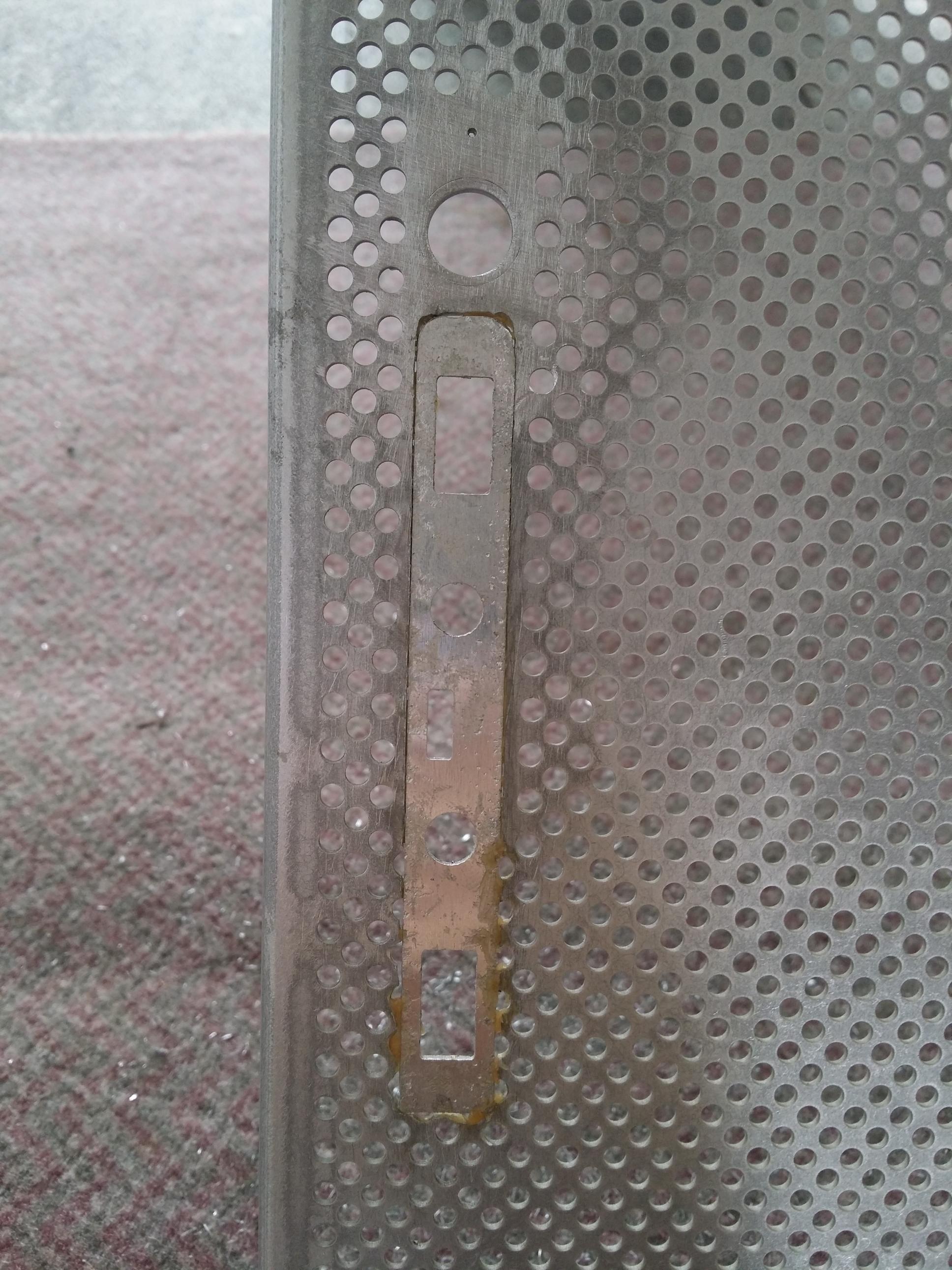
For the front IO panel you need to rasp the aluminium piece until it fits into the hole from the original IO place.
Then you can glue it in, and use aluminium putty to fill the remaining cracks or holes.
Concerning the panel, which holds the fans and radiator (5th picture on the right); the panel itself is just being held by the two horizontal panel, which are screwed into the original case.
Hope this helped 🙂
Hi, I realize that this was a while ago but I was wondering since I don’t know anything about CADfiles. Could I just take the file you have provided to a lasercutter and they will get the measurements from it or do I need to measure it myself? After looking all over for a way to update the front panel, besides with the modded cables, this seems to be the only option left. Even though it will probably mean I have to sand down and repaint the whole case just to update this small spot.
Kind Regards
Christoffer
Hi Christoffer,
yes this will work.
Take those dxf files to a lasercutter shop and it will work.
At the shop where I ordered them, they even had an online preview.
This helps to do a last minute check, so that you can be sure they will process them correctly.
Concerning the front panel that seems to be the only option. The back needs to be also painted.
Best regards
Thomas
2025 and this is still helping people !
Great posts .!